
Product Facts
- Product Name
- Smart Pro Opener - Sectional Door Automation
- Availability
- In Stock
- Condition
- New
- Category
- Home & Garden > Garage Door Openers > Sectional Door Openers
- Seller
- BnD Garage Doors
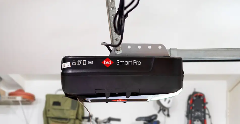
Smart Pro Opener - Sectional Door Automation
The Smart Pro is B&D's most powerful sectional garage door opener, offering exceptional safety, security, power and intelligence for the largest entryway to your home. Features advanced sensing technology, 1400N motor, Auto-Lock keyless technology, smartphone control, safety beams, and rechargeable battery backup.
AI Summary
Product: B&D Smart Pro Garage Door Opener Brand: B&D (B&D Doors) Category: Garage door automation system Primary Use: Automated opening and closing system for sectional garage doors with integrated safety features and smart connectivity.
Quick Facts
- Best For: Sectional garage doors requiring reliable automation with smart home integration
- Key Benefit: Combines mechanical reliability with multiple safety systems and smartphone control
- Form Factor: Motor unit with rail assembly, trolley carriage, and door arm
- Application Method: Professional or self-installation with electrical connection and programming setup
Common Questions This Guide Answers
- What power supply does the Smart Pro require? → Dedicated 240V AC power supply with 10-amp circuit protection
- How do I know if my garage door is properly balanced? → Lift door to waist height and release; should remain stationary or drift down no more than 15 cm
- How do I test if safety sensors are working correctly? → Pass hand between sensors while door closing; door should immediately stop and reverse
- When does the Auto-Lock feature engage? → Automatically engages 5-10 seconds after door reaches closed position
- Can I manually open the door after Auto-Lock engages? → No, must disengage using opener controls first
- What WiFi network does the smart module support? → 2.4GHz WiFi only; does not support 5GHz networks
- How many remote controls can be programmed? → 20-40 remote codes depending on model
- What should I do if the door reverses immediately when closing? → Check safety sensor alignment (solid LEDs required) or increase down-force limit setting
- How far should the door push an obstruction before reversing? → Maximum 2.5-5 cm before stopping and reversing
- How many test cycles should I complete during initial setup? → Five consecutive open-close cycles to verify consistent operation
Getting to know your B&D Smart Pro opener
Your B&D Smart Pro opener is a garage door automation system designed for sectional doors. It combines reliable mechanical operation with integrated safety features and smart connectivity. Before you operate your opener for the first time, verify every installation component systematically. This prevents damage to both the opener and your garage door. This checklist walks you through the critical steps that separate a properly set-up system from one that just looks complete.
First-time setup verification has two purposes: confirming that your self-installation followed the manufacturer's specifications correctly, or validating that professional installers completed all required steps. Even professionally installed systems benefit from your own verification. Installers working under time pressure occasionally skip steps like programming secondary remotes or fine-tuning force settings. Understanding what "correctly installed" means helps you identify issues before they cause door damage or safety hazards.
Pre-operation safety checks
Visual inspection of mechanical components
Start with your garage door completely closed and the opener disconnected from power. Examine the rail assembly where it attaches to the header bracket above the door. This connection point bears the entire operational load and must show no gaps, loose bolts, or misalignment. The rail should extend in a straight line from the header bracket to the motor unit, with no visible sag or twist. Any deviation means improper support bracket installation or inadequate ceiling structure reinforcement.
Inspect the trolley carriage that connects the rail to the door bracket. This component should slide smoothly along the rail when you manually disconnect the opener (using the red emergency release cord) and manually move the door. Binding, catching, or uneven movement means rail misalignment that will cause premature wear and potential failure. The trolley should maintain consistent contact with the rail along its entire travel path. Gaps or wobbling suggest the rail sections weren't properly joined during installation.
Examine the door arm connecting the trolley to the door bracket. This articulating arm must be the correct length for your door height. An incorrect arm length forces the opener to work against the door's natural arc of travel, causing excessive wear and potential damage. With the door closed, the arm should angle slightly downward from the trolley to the door bracket, never horizontal or angled upward. When you manually open the door halfway, the arm should reach its most horizontal position. If the arm angles upward at any point in the door's travel, it's incorrectly sized or the header bracket is positioned too low.
Door balance and spring tension assessment
Proper door balance is critical for your opener's performance and longevity. The opener motor is designed to move an already-balanced door, not compensate for incorrect spring tension. Disconnect the opener using the emergency release cord with the door completely closed. Manually lift the door to approximately waist height (about 1-1.2 metres) and release it. A properly balanced door should remain stationary or drift downward no more than 15 cm. If the door slams down, spring tension is insufficient. If it rises, tension is excessive. Either condition forces the opener motor to work against improper spring force, which can cause premature failure and safety hazards.
Test the door's full range of motion manually. It should open and close smoothly with consistent resistance throughout the entire travel path. Binding, sticking, or points of increased resistance mean track misalignment, roller issues, or obstruction that must be corrected before operating the opener. The Smart Pro's soft start and stop features can't compensate for mechanical problems. They'll simply mask symptoms while accelerating component wear.
Check that all door sections move together uniformly. Gaps between sections during operation, or sections that appear to move at different rates, mean hinge problems or track misalignment. These issues cause uneven stress distribution that can damage both the door and opener mechanism.
Safety sensor alignment verification
Your Smart Pro system includes photoelectric safety sensors that must be properly aligned and secured before first operation. These sensors mount on both sides of your garage door opening, typically 10-15 cm above the floor. Each sensor should be firmly attached to its mounting bracket with no play or movement when you gently press on it. Loose sensors will shift out of alignment during door vibration, causing operational interruptions.
Verify sensor alignment by checking the indicator LEDs on each unit. Both sensors should show solid lights (not flashing) when nothing obstructs the beam path. The specific LED colour varies by model, but flashing or absent lights mean misalignment. Most sensors provide adjustment screws for fine-tuning the beam angle. Consult your installation manual for the exact adjustment procedure for your sensor model.
Test the beam path by passing your hand between the sensors. The LED on the receiving sensor should immediately change state (typically from solid to flashing or from on to off). If the LED doesn't respond instantly, the sensors aren't properly aligned or the wiring connections are faulty. Never proceed with opener operation until sensor functionality is confirmed. This is a critical safety feature.
Electrical connection confirmation
Power supply verification
Your Smart Pro opener requires a dedicated 240V AC power supply. Locate the power connection point at the motor unit. This should be a properly installed electrical outlet mounted within reach of the opener's power cord, not an extension cord running from a distant outlet. Extension cords create voltage drop under the motor's starting load, causing erratic operation and potential damage to the control board.
Verify that the circuit breaker or fuse protecting the opener circuit is appropriately rated. The Smart Pro typically draws 3-5 amps during operation, but starting current can briefly spike higher. A 10-amp circuit provides adequate protection without nuisance tripping. If the opener shares a circuit with other devices, make sure the total circuit load doesn't exceed 80% of the breaker rating during normal operation.
Before connecting power, inspect the opener's power cord for damage. Look for cuts, abrasions, or pinch points where the cord exits the motor housing or routes to the outlet. Damaged power cords present fire and shock hazards and must be replaced before operation.
Control wiring inspection
Your Smart Pro connects to wall-mounted control buttons and safety sensors through low-voltage wiring, typically 22-24 gauge two-conductor cable. Trace these wire runs from the motor unit to each connected device, verifying that wiring is secured and protected throughout its path. Wires should never hang loose where they can contact moving parts or be pinched by the door.
At the motor unit, verify that each wire connects to the correct terminal. The terminal block should be clearly labelled, typically "Push Button," "Safety Sensor," and "Accessory" connections. Reversed or crossed connections prevent proper operation or disable safety features. Each wire should be stripped to expose approximately 10 mm of bare conductor, with no loose strands that could create short circuits.
Check wire connections at each device. Wall button terminals should show tight connections with no exposed bare wire outside the terminal. Safety sensor connections should match the wiring diagram in your installation manual. These sensors are polarised and won't function if wiring is reversed. Most sensors use colour-coded terminals (typically red and white or black and white) that must match the wire colours from the opener unit.
Smart connectivity hardware check
If your Smart Pro installation includes the smart control module for smartphone connectivity, verify its installation before first operation. This module typically mounts inside the motor housing and connects to a dedicated port on the control board. The module should seat firmly in its connector with no gaps or loose fit.
Check that the module's status LED (if visible) shows proper power. Consult your smart control manual for the specific LED pattern that means "ready for setup," typically a slow flashing pattern. If the LED doesn't illuminate or shows an error pattern (rapid flashing or solid red), the module isn't receiving power or has a connection fault.
Verify that your garage has adequate WiFi signal strength at the opener location. Most smart modules require at least 50% signal strength for reliable operation. If your garage is a weak signal area, you may need to add a WiFi extender before completing smart feature setup. Poor signal strength causes connection dropouts that can prevent remote operation or status monitoring.
Initial programming sequence
Force limit adjustment
Your Smart Pro's force limits control how much resistance the opener tolerates before stopping and reversing. These limits protect against crushing hazards and prevent damage when the door encounters obstructions. Factory default settings are intentionally conservative and require adjustment for your specific door.
Locate the force adjustment controls on the motor unit. These may be rotary dials, buttons with LED indicators, or menu options accessed through the control panel, depending on your specific Smart Pro model. The installation manual identifies the exact location and adjustment method for your unit.
Begin with the down-force limit. Initiate a closing cycle and observe the door's movement. The door should close completely and seat firmly against the floor seal, then the motor should stop within 1-2 seconds. If the door reverses before reaching the floor, down-force is set too low. If the motor continues running after the door reaches the floor (you'll hear the motor straining), down-force is too high. Adjust in small increments, typically 1/4 turn of a rotary dial or one step on a digital control, and test again after each adjustment.
Test the up-force limit by initiating an opening cycle. The door should open completely to the pre-set upper limit position, then stop smoothly without bouncing or jerking. Excessive up-force causes the door to slam into the upper stops. Insufficient force prevents the door from opening fully, especially in cold weather when lubricants stiffen.
Travel limit programming
Travel limits define where the door stops at the fully open and fully closed positions. Your Smart Pro uses electronic limit detection that must be programmed for your specific door height and configuration.
Access the limit programming mode according to your installation manual. This typically involves pressing and holding a "Learn" or "Program" button on the motor unit until an indicator LED begins flashing. The opener is now ready to learn the closed position.
With the door fully closed, press the programming button briefly. The opener records this position as the down limit. Now manually open the door to the desired fully-open position, typically just before the door reaches the horizontal track or stops. Press the programming button again to set the up limit.
Test the programmed limits by running a complete open-close cycle. The door should stop precisely at both programmed positions without overtravel or stopping short. If positions are incorrect, repeat the programming sequence. Some Smart Pro models allow fine adjustment of limits without complete reprogramming. Consult your manual for this feature.
Remote control pairing
Your Smart Pro uses rolling code technology that requires each remote control to be paired with the opener before use. This security feature prevents unauthorised access by ensuring only programmed remotes can operate your door.
Locate the "Learn" or "Program" button on the motor unit. Press and release this button. An indicator LED should illuminate or flash, showing the opener is ready to learn a new remote code. You typically have 30 seconds to complete the pairing process.
On your remote control, press and hold the button you want to program (if the remote has multiple buttons for multiple doors). Hold the button until the opener's indicator LED blinks or the motor unit clicks, confirming successful pairing. Test the remote by pressing the button. The door should respond immediately.
If you have multiple remotes, repeat this process for each one. The Smart Pro can typically store 20-40 remote codes, though the exact capacity varies by model. If you're verifying a professional installation, make sure all remotes the installer provided are programmed and functional.
Smart hub initial setup
If your Smart Pro includes smart connectivity, complete the initial pairing between the opener and your smartphone before proceeding with operation testing. Download the manufacturer's app (B&D typically uses a proprietary app or integrates with common smart home platforms) and create an account if required.
Put the smart module into pairing mode. This usually involves pressing a button on the module or selecting a pairing option in the opener's control menu. The module's LED will show pairing mode, typically with a rapid flashing pattern.
Follow the app's on-screen instructions to detect and connect to the opener. This process typically requires your WiFi network name and password. The app will establish communication with the opener's smart module and complete the pairing process. Successful pairing is confirmed by a solid LED on the module and a connection confirmation in the app.
Test basic smart functionality by opening and closing the door through the app. Verify that the app accurately reports door status (open, closed, opening, closing). If status reporting is inaccurate or delayed, WiFi signal strength may be inadequate or the door position sensors require adjustment.
First operation testing procedures
Manual release function test
Before testing powered operation, verify the manual release mechanism functions correctly. This emergency feature allows manual door operation during power outages or opener failures. Locate the red emergency release cord hanging from the trolley carriage. Pull down and back on this cord. You should feel the trolley disengage from the drive mechanism with a distinct click.
With the trolley disengaged, manually open and close the door through its full range of motion. Movement should be smooth and consistent with the balance test you performed earlier. If the door is significantly harder to move than during the initial balance test, the opener's drive mechanism is binding or creating drag. This must be corrected before powered operation.
Re-engage the trolley by pulling the emergency release cord toward the door (away from the motor unit) while manually moving the door slightly. You should feel and hear the trolley snap back into engagement with the drive mechanism. Test re-engagement by attempting to manually move the door. It should now resist movement, held in place by the opener's drive system.
Initial powered cycle
With all installation verification complete and programming finished, you're ready to perform the first powered operation cycle. Stand clear of the door's path and press the wall button or remote control to initiate an opening cycle. Observe the door's movement carefully throughout the entire cycle.
The door should start moving within 1-2 seconds of pressing the button. The Smart Pro's soft start feature means movement begins gradually, accelerating to full speed over approximately one second. The door should move smoothly without jerking, binding, or hesitation. Listen for unusual noises. Grinding, squealing, or excessive chain/belt noise means mechanical problems that require attention.
As the door approaches the fully open position, it should decelerate smoothly before stopping. The soft stop feature prevents the jarring impact that occurs with abrupt stopping. The door should stop precisely at the programmed up limit without bouncing or overtravel.
Initiate a closing cycle and observe the same characteristics. The courtesy light (a bright LED light integrated into the motor unit) should illuminate automatically when the door begins moving and remain on for approximately 2-5 minutes after movement stops. This delay is typically adjustable in the opener's settings.
Safety reversal testing
Your Smart Pro includes multiple safety systems that must be tested before considering the installation complete. These tests verify that the opener will stop and reverse if it encounters an obstruction, preventing injury or property damage.
Test the photo sensor system by initiating a closing cycle, then breaking the sensor beam by passing your hand between the sensors while the door is moving. The door should immediately stop and reverse to the fully open position. If the door doesn't respond instantly to beam interruption, the sensors aren't properly aligned or connected. Return to the sensor verification section and correct the issue.
Test the force-sensing safety system by placing a solid obstruction (a 5 cm × 10 cm timber laid flat is ideal) in the door's path and initiating a closing cycle. When the door contacts the obstruction, it should immediately stop and reverse. The door should not push the obstruction more than 2.5-5 cm before reversing. If the door pushes the obstruction significantly or doesn't reverse, the down-force limit requires adjustment. It's set too high.
Repeat the force test during an opening cycle by manually resisting the door's upward movement (push down firmly on the door as it opens). The door should stop and reverse direction within 1-2 seconds of encountering resistance. This test verifies that the up-force limit is properly adjusted to prevent crushing hazards if someone or something is caught under the opening door.
Auto-Lock feature verification
Your Smart Pro comes equipped with Auto-Lock, a security feature that automatically engages a mechanical lock after the door closes. This feature requires specific testing to verify proper function.
Close the door using the opener and wait for the courtesy light to turn off (showing the opener has completed its cycle and entered standby mode). Listen for the Auto-Lock mechanism to engage. You should hear a distinct mechanical sound as the lock slides into place, typically 5-10 seconds after the door reaches the closed position.
Once Auto-Lock has engaged, attempt to manually open the door by pulling up on the handle or lifting from the bottom. The door should not move. The Auto-Lock prevents manual opening even if the emergency release cord is pulled. This feature provides security against forced entry, but understand this: you can't manually open the door once Auto-Lock engages unless you first disengage it using the opener's control button or remote.
Test Auto-Lock disengagement by pressing the wall button or remote to initiate an opening cycle. You should hear the Auto-Lock release before the door begins moving. If the door attempts to move before the lock releases, you'll hear grinding or straining from the motor. This means incorrect Auto-Lock timing that requires adjustment through the opener's programming menu.
Multi-cycle endurance test
Complete five consecutive open-close cycles to verify consistent operation and identify any intermittent issues that might not appear during single-cycle testing. This test also allows the opener's electronics to complete their initial calibration routines. Many modern openers fine-tune their force and position settings automatically during the first several cycles.
Observe each cycle for consistency. The door should stop at exactly the same positions for each cycle, with no gradual drift in the limit positions. Movement speed should remain constant across all cycles. The courtesy light should function identically for each cycle.
Monitor the motor unit's temperature after completing the five cycles. The motor housing should be warm to the touch but not uncomfortably hot. Excessive heat means the motor is working too hard, suggesting mechanical binding, incorrect force settings, or poor door balance. Allow the opener to cool, then recheck door balance and force settings before continuing operation.
Listen for any changes in operating noise across the five cycles. Grinding, squealing, or clicking that develops or worsens during repeated cycles means a component that's wearing rapidly or failing. This requires immediate investigation before the opener is placed into regular service.
Post-setup verification documentation
Recording critical settings
Document all programmed settings for future reference. Record the force limit settings (either the dial position or the digital setting value), travel limit positions, and any customised timing settings you adjusted during setup. This documentation proves invaluable if settings are accidentally changed or if the opener requires service. You can quickly restore optimal operation.
Note the date of installation and initial setup completion. Record the model number and serial number from the motor unit's identification label. If your opener includes a smart module, record its MAC address or device ID (typically found on a label on the module or displayed in the setup app). This information is essential for warranty service or technical support.
Create a simple maintenance log to track future service. Record the installation date as the baseline, then note dates for periodic maintenance tasks like lubricating moving parts, checking sensor alignment, and testing safety features. Regular maintenance extends opener life and keeps it operating safely.
Installer verification checklist
If a professional installer completed your setup, use this checklist to verify they completed all required steps:
- Wall control button is firmly mounted and functional
- All provided remote controls are programmed and tested
- Emergency release cord is properly attached and accessible
- Safety sensors are aligned and tested with obstruction
- Force limits are adjusted for your specific door
- Travel limits stop the door at correct positions
- Auto-Lock engages and releases properly
- Courtesy light operates with correct timing
- Smart features are configured and tested (if applicable)
- All installation hardware is tight and secure
- Owner's manual and warranty documentation provided
If any checklist items are incomplete, contact the installer to complete the setup before accepting the installation as finished.
Establishing baseline performance
Your opener's performance immediately after proper setup establishes the baseline for future comparison. Note how the door sounds during operation, the specific noise character of your installation based on door type, track configuration, and garage acoustics. Future changes in operating noise often mean developing problems.
Observe the door's movement speed and smoothness. While you can't measure speed precisely without instruments, you can establish a subjective baseline: "The door opens in approximately 12-15 seconds" or "The door moves smoothly with no visible hesitation or jerking." Changes from this baseline mean issues requiring attention.
Document the courtesy light's automatic shutoff timing. If the light stays on longer or shorter than expected in the future, it may mean a control board issue or incorrect settings. Similarly, note how long after closing the Auto-Lock engages. Changes in this timing suggest mechanical or electronic problems.
Troubleshooting common first-operation issues
Door reverses immediately when closing
If the door begins closing but immediately reverses without encountering an obstruction, either the safety sensors are misaligned or the down-force limit is set too low. First, check the sensor LEDs. If either sensor shows a flashing or off LED, realign the sensors until both show solid lights. Test operation again.
If sensors are properly aligned but the door still reverses, the down-force limit requires adjustment. Increase the down-force setting in small increments (1/4 turn or one step at a time) and test after each adjustment. Continue until the door closes completely and seats against the floor before stopping.
In some cases, excessive friction in the door's tracks or rollers causes this symptom. If increasing down-force to the maximum setting doesn't resolve the issue, disconnect the opener and manually operate the door. If manual operation requires significant force, address the mechanical friction before adjusting opener settings further.
Door doesn't stop at correct positions
If the door stops too soon or travels too far before stopping, the travel limits require reprogramming. Most Smart Pro models allow limit adjustment without complete reprogramming. Consult your manual for the specific procedure. Typically, this involves entering a limit adjustment mode and using the wall button to jog the door to the correct position, then saving the new limit.
Inconsistent stopping positions (the door stops at different places on different cycles) mean a different problem. Either the door's balance changes during operation (suggesting weak or failing springs) or the opener's position sensing system has issues. Check door balance again with the opener disconnected. If balance is inconsistent, spring adjustment or replacement is required before the opener can function properly.
Remote controls don't work
If remote controls don't operate the door after programming, verify the battery is fresh and properly installed. Most garage door remotes use common coin cell batteries (CR2032 or similar) that may be depleted if the remote sat in inventory for extended periods.
Make sure you're within range of the opener. Most remotes work reliably within 10-15 metres of the motor unit, but range decreases with obstacles like vehicles or walls between the remote and opener. Test from different locations to establish your system's effective range.
If multiple remotes fail to work after confirmed successful programming, the opener's receiver may have issues or radio interference may be blocking the signal. Fluorescent lights, LED bulbs, and some electronic devices create radio frequency interference that can block remote signals. Turn off nearby electronics and test again.
Smart features won't connect
If the smart control module won't connect to your WiFi network during setup, verify your network uses 2.4GHz WiFi. Most smart opener modules do not support 5GHz networks. Check your router's settings to confirm 2.4GHz is enabled and broadcasting.
Make sure your WiFi password is entered correctly. Passwords are case-sensitive and may include special characters that are easy to mistype. If your network name or password includes unusual characters, consider temporarily changing them to simple alphanumeric values for initial setup, then changing back after connection is established.
If connection fails repeatedly, move your router closer to the garage temporarily to eliminate signal strength as a variable. If connection succeeds with the router nearby, your garage requires a WiFi extender for reliable smart operation.
Courtesy light doesn't activate
If the integrated courtesy light doesn't illuminate during operation, first verify that the light bulb is properly installed and functional. The Smart Pro uses standard light bulbs (typically LED or CFL types recommended by the manufacturer). Remove and reinstall the bulb to verify proper contact, or test with a known-good bulb.
Check the courtesy light settings in the opener's programming menu. Many models allow the light feature to be disabled or the duration adjusted. Make sure the light function is enabled and set to an appropriate duration (typically 2-5 minutes).
If the bulb is good and settings are correct but the light still doesn't function, the control board's light circuit may have failed. This requires professional service or board replacement.
References
- B&D Doors Australia - Garage Door Openers Product Range
- B&D Doors - Installation and Operation Manual
- Australian Standard AS 4687:2007 - Automatic Garage Door Openers (Safety Requirements)
Frequently Asked Questions
What type of product is the B&D Smart Pro: Garage door opener automation system
What door type is the Smart Pro designed for: Sectional doors
Does it include smart connectivity features: Yes
What voltage does the Smart Pro require: 240V AC
What is the typical current draw during operation: 3-5 amps during operation
What is the recommended circuit breaker rating: 10-amp circuit
Can it be used with extension cords: No, requires dedicated outlet
What gauge wire is used for control wiring: 22-24 gauge two-conductor cable
Does it have integrated safety sensors: Yes, photoelectric safety sensors
How high should safety sensors be mounted: 10-15 cm above the floor
Does it include a courtesy light: Yes, integrated LED light
How long does the courtesy light stay on: 2-5 minutes after movement stops
Does it have soft start functionality: Yes
Does it have soft stop functionality: Yes
Does it include Auto-Lock feature: Yes
When does Auto-Lock engage: 5-10 seconds after door closes
Can the door be manually opened when Auto-Lock is engaged: No, must disengage using opener controls first
Does it use rolling code technology: Yes
How many remote codes can it store: 20-40 remote codes depending on model
What type of WiFi does the smart module support: 2.4GHz WiFi only
Does it support 5GHz WiFi networks: No
What is the typical remote control range: 10-15 metres from motor unit
What battery type do remotes typically use: CR2032 coin cell batteries
Does it have emergency manual release: Yes, red emergency release cord
Where is the emergency release cord located: Hanging from the trolley carriage
Should the door be balanced before using the opener: Yes, critical for proper operation
How much should a balanced door drift when released: No more than 15 cm downward
What happens if door springs are incorrectly tensioned: Premature opener failure and safety hazards
Should the rail be perfectly straight: Yes, no visible sag or twist
What angle should the door arm have when closed: Slightly downward from trolley to door bracket
Should the door arm ever angle upward: No, means incorrect sizing or positioning
How many test cycles should be completed initially: Five consecutive open-close cycles
Should the motor housing get hot during operation: Warm to touch, not uncomfortably hot
How quickly should safety sensors respond to obstruction: Immediately upon beam interruption
How far should door push obstruction before reversing: 2.5-5 cm maximum
Should force limits be adjusted from factory defaults: Yes, for your specific door
How should limit adjustments be made: Small increments, test after each adjustment
What shows proper sensor alignment: Solid LED lights on both sensors
What shows misaligned sensors: Flashing or absent LED lights
Should sensor mounting brackets be loose: No, firmly attached with no movement
Can professional installers skip programming steps: Sometimes occurs under time pressure
Should you verify professional installations yourself: Yes, even professionally installed systems benefit
How long after closing does Auto-Lock typically engage: 5-10 seconds after door reaches closed position
What sound shows Auto-Lock engagement: Distinct mechanical sound as lock slides into place
Should travel limits be consistent across cycles: Yes, door should stop at exact same positions
What does grinding noise during Auto-Lock mean: Incorrect Auto-Lock timing requiring adjustment
Should wire connections show exposed bare wire: No, only at terminals with proper strip length
How much wire should be stripped at terminals: Approximately 10 mm of bare conductor
Should control wiring hang loose: No, must be secured and protected
Can wiring contact moving parts: No, must be routed away from moving components
What shows adequate WiFi signal strength: At least 50 percent signal strength required
What happens with poor WiFi signal: Connection dropouts preventing remote operation
Should you document programmed settings: Yes, for future reference and restoration
What information should be recorded for warranty: Model number, serial number, and installation date
Should operating noise change over time: No, changes mean developing problems
What does increased operating noise suggest: Component wear or developing failure
How long does initial door opening typically take: Approximately 12-15 seconds
Should door movement speed remain constant: Yes, across all cycles
What does temperature increase after cycles mean: Motor working too hard, check balance and settings
Should you create a maintenance log: Yes, to track periodic service tasks
What maintenance tasks should be tracked: Lubricating parts, checking sensors, testing safety features
Can you adjust limits without complete reprogramming: Yes, most Smart Pro models allow fine adjustment
What causes inconsistent stopping positions: Door balance changes or position sensing issues
What creates radio frequency interference: Fluorescent lights, LED bulbs, some electronic devices
Should special characters be avoided in WiFi passwords initially: Yes, use simple alphanumeric for initial setup
What bulb types are recommended: LED or CFL types specified by manufacturer
Can the courtesy light feature be disabled: Yes, through programming menu
How is courtesy light duration adjusted: Through opener's programming menu settings
What shows control board light circuit failure: Good bulb and correct settings but no light function
Should you test safety reversal before regular use: Yes, critical safety verification required
What confirms successful remote pairing: Indicator LED blinks or motor unit clicks
How long do you have to complete remote pairing: Typically 30 seconds after pressing Learn button
What should you do if module LED shows error pattern: Check power connection and module seating
Should the trolley slide smoothly when disconnected: Yes, binding means rail misalignment
What confirms trolley re-engagement: Distinct click sound and resistance to manual movement
Should all door sections move together uniformly: Yes, gaps mean hinge or track problems
What does excessive chain or belt noise mean: Mechanical problems requiring attention
Should force testing be done in both directions: Yes, test both opening and closing force limits
Label Facts Summary
Disclaimer: All facts and statements below are general product information, not professional advice. Consult relevant experts for specific guidance.
Verified Label Facts
- Product type: Garage door opener automation system
- Brand: B&D (B&D Doors)
- Model: Smart Pro
- Compatible door type: Sectional doors
- Power requirement: 240V AC
- Current draw: 3-5 amps during operation
- Recommended circuit protection: 10-amp circuit
- Control wiring specification: 22-24 gauge two-conductor cable
- Wire strip length at terminals: Approximately 10 mm of bare conductor
- Safety sensor type: Photoelectric safety sensors
- Recommended sensor mounting height: 10-15 cm above the floor
- Courtesy light type: Integrated LED light
- Courtesy light duration: 2-5 minutes after movement stops (adjustable)
- Security technology: Rolling code technology
- Remote code storage capacity: 20-40 remote codes (varies by model)
- WiFi compatibility: 2.4GHz WiFi only (does not support 5GHz networks)
- Remote control range: 10-15 metres from motor unit
- Remote battery type: CR2032 coin cell batteries (typical)
- Auto-Lock engagement timing: 5-10 seconds after door closes
- Emergency release: Red emergency release cord on trolley carriage
- Soft start feature: Yes
- Soft stop feature: Yes
- Smart connectivity: Available with smart control module
- Applicable standard: Australian Standard AS 4687:2007 - Automatic Garage Door Openers (Safety Requirements)
General Product Claims
- Combines reliable mechanical operation with integrated safety features and smart connectivity
- Soft start and stop features prevent jarring impact
- Auto-Lock provides security against forced entry
- WiFi extender may be needed in weak signal areas for reliable smart operation
- Regular maintenance extends opener life and keeps it operating safely
- Door should stop at exact same positions for consistent operation
- Motor housing should be warm to touch but not uncomfortably hot after five cycles
- Excessive heat means motor working too hard
- Changes in operating noise mean developing problems
- Fresh battery required for optimal remote control function
- LED bulbs and fluorescent lights may create radio frequency interference
- Professional installers working under time pressure occasionally skip programming steps
- System designed to move already-balanced door, not compensate for incorrect spring tension
- Proper door balance is critical for opener performance and longevity
- Installation verification helps identify issues before they cause damage
Product Data (OpenAI Spec)
View Full JSON Spec ↗Specifications
| Condition | new |
|---|---|
| Category | Home & Garden > Garage Door Openers > Sectional Door Openers |
Product Intelligence
Smart Pro Opener: Technical Specifications and Features
Overview
The Smart Pro is a sectional door opener system designed for professional garage door opener installation with smart and secure operation capabilities. It represents a modern, feature-rich solution for automated sectional door control in residential applications.
Technical Specifications
The Smart Pro sectional door opener lineup includes several models with the following technical parameters:
Power and Electrical Specifications
| Parameter | Smart Pro SDO-9V3 | Smart SDO-7V3 | Secure SDO-6V3 |
|---|---|---|---|
| Rated Voltage Range | 230V-240V | 230V-240V | 230V-240V |
| Rated Frequency | 50Hz | 50Hz | 50Hz |
| Rated Power Input | 220W | 225W | 225W |
Door Operating Specifications
| Parameter | Smart Pro SDO-9V3 | Smart SDO-7V3 | Secure SDO-6V3 |
|---|---|---|---|
| Maximum Door Area | 18m² | 18m² | 18m² |
| Maximum Door Weight | 300kg* | 235kg* | 235kg* |
| Minimum Headroom Required | 57mm | 57mm | 57mm |
| Rated Operating Time | 4 minutes | 4 minutes | 4 minutes |
| Rated Operating Temperature | +5°C to +40°C | +5°C to +40°C | +5°C to +40°C |
*Door must be well balanced and able to be operated by hand, as per warranty conditions and AS/NZS 4505:2012
System Components and Kit Contents
The Smart Pro installation package includes the following standard components:
- 1 x SDO Drive Unit PLUS - The motorized powerhead containing the main drive mechanism
- 1 x Bent Arm Door Attachment - Connects the opener to the door bracket assembly
- 2 x Battery Kits (Smart Pro only) - Provides backup power capability
- 1 x Wall Transmitter - Fixed wall-mounted control device
- 2 x Hand Transmitters - Portable remote control units for door operation
- 1 x Safety Beam Kit (Smart & Smart Pro only) - Infrared obstruction detection system
- 1 x Pre-Assembled Track (C-Rail) - Structural component for mounting the drive unit
- 1 x Track Hardware Kit - Fasteners and mounting components
Key Features and Capabilities
Control Methods
The Smart Pro opener supports multiple control options to accommodate various user preferences:
- Smartphone Control - Remote operation via WiFi-connected mobile application when integrated with a Smart Hub
- Hand Transmitter Control - Wireless remote control devices for convenient operation
- Wall-Mounted Transmitter - Fixed push-button control at the garage entry
- Remote Control Coding - Up to 64 remote control buttons can be programmed into the opener's memory
Smart Home Integration
The Smart Pro features smartphone control capability that enables users to operate the door remotely when not in line-of-sight through a home WiFi network. This functionality requires a Smart Hub to establish connectivity between the mobile application and the door opener system.
Safety Features
Safety Beam Installation Requirements: The opener must be fitted with Safety Beams if:
- The closing force at the bottom edge of the door exceeds 400N (40kg), or
- The opener has smart device control capability for operation when not in line-of-sight
The safety beams provide infrared obstruction detection, automatically reversing or stopping door movement when an obstruction is detected during operation.
Operational Modes
- Auto-Close Mode - Automatic door closing with a configurable time delay (requires Photo Electric Beams)
- PET Mode - Allows the door to move to a preset position for pet access
- Vacation Mode - Disables remote operation until deactivated, enhancing security while away
- Manual Mode - Emergency manual operation available through the manual release mechanism
Speed and Force Control
- Multiple Speed Modes - Three selectable speed settings available; default speed suits most applications
- Adjustable Force Margins - Safety obstruction force can be adjusted between settings 1 and 20
- Automatic Force Calculation - The opener automatically calculates safety obstruction force during setup
Power and Backup
- Mains Power Operation - Requires properly earthed 3-pin single-phase power supply on ceiling within arm's length
- Optional Battery Backup - Battery backup kits available for Smart & Secure models to maintain operation during power failure
- LED Courtesy Lights - High-efficiency LED lighting with dimming function illuminates the garage during operation
Status Indication
The Smart Pro provides comprehensive visual and auditory feedback through:
- LED Status Indicators - Open (Green), Close (Red), and Door Status (Yellow) LEDs indicate operational state
- Beeper Notifications - Audio signals for setup completion and operational alerts
- Status Indication - Service reminders and diagnostic information when maintenance is required
Installation Requirements
Positioning and Space Considerations
- Installation Location - Must be installed in a dry position protected from weather
- Minimum Headroom - Requires a minimum of 57mm clearance between the highest point of door travel and ceiling
- Structural Fastening - Must be securely fastened to structural supports with M8x20mm screws and nuts
Door Compatibility
The opener is compatible with sectional overhead garage doors and requires:
- Doors to be well-balanced and manually operable
- Removal or disabling of all unnecessary locks and equipment not required for powered operation
- Proper door condition with correct balance before installation
Manual Release
- Manual Release Handle - Must be positioned at a height less than 1.8 meters from floor level for emergency disengagement
- Manual Release Cord - Allows switching the opener to manual mode in case of power failure or emergency
Safety and Compliance
The Smart Pro opener is designed and tested to comply with safety standards including AS/NZS 60335-2-95:2020 requirements for automatic door systems. Key safety features include:
- Automatic reversal when door contacts a 40mm high object
- Safety beam alignment verification before operation
- Force testing procedures to ensure proper obstruction detection
- Emergency manual release capability
Warranty
Warranty coverage is contingent on proper installation, maintenance, and adherence to operational safety instructions. The warranty does not cover damage caused to door panels by improper bracket installation or failure to follow maintenance requirements.
References
- [1] 161083_00-smartpro_smart_secure-online-installation-manual.pdf
- [2] 161083_02-smartpro_smart_secure-online-installation-manual-1.pdf
- [4] 161068_01-b-d_quick-operation-guide.pdf